
A frame-style hand-operated jig built for bare motherboard (MB) board testing, with a transparent press plate and probe array aligned across the bare PCB surface.
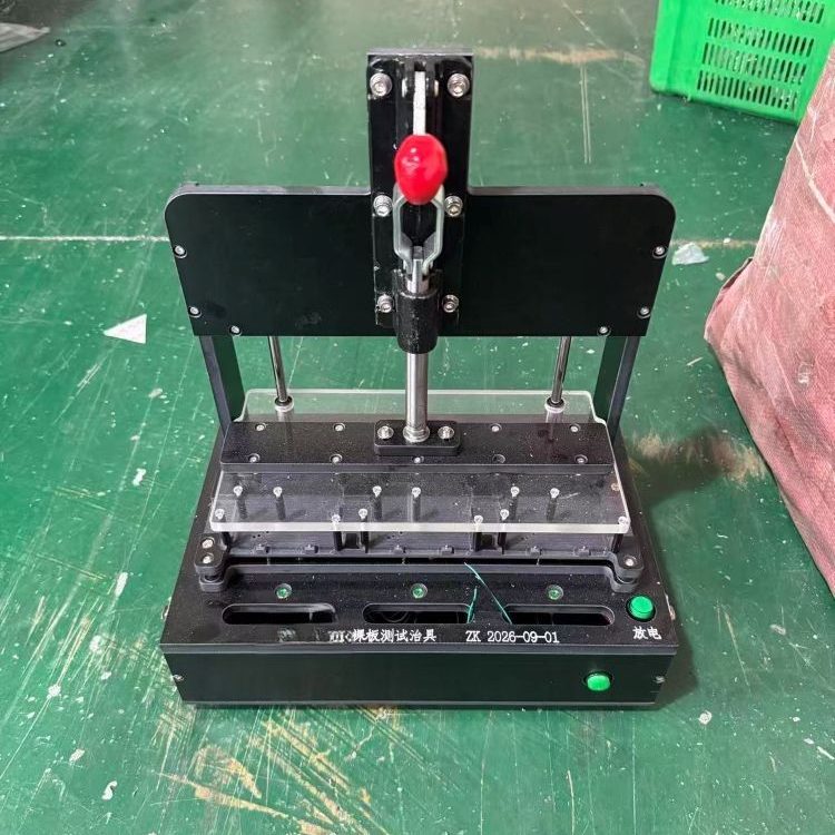
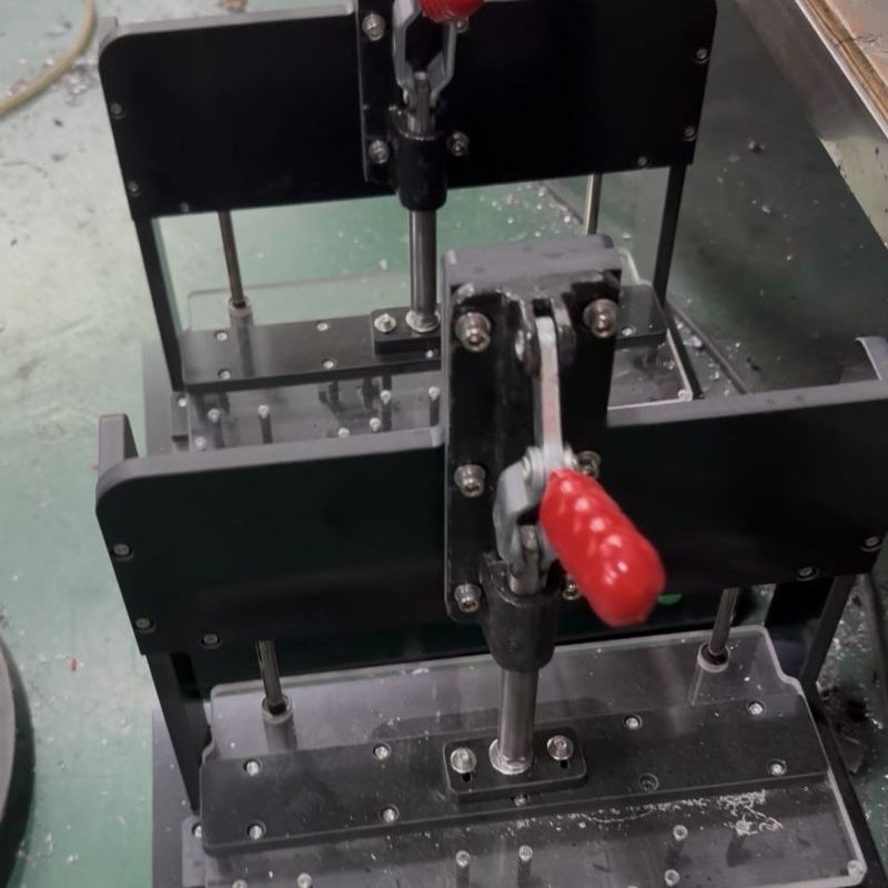
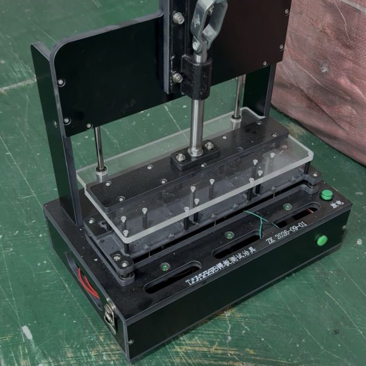
This jig is dedicated to bare MB boards before components or housing are added. The black upright frame carries a central red-handle toggle clamp that lowers the transparent acrylic press plate and probe array onto the exposed board. Guide rods keep the plate level as it descends, and green start buttons plus a discharge switch sit on the front base. Because the board has no enclosure, locating pins and probe positions are arranged around the bare PCB outline, making it suitable for early-stage motherboard circuit validation rather than finished product testing.
Key Features
- Purpose-built for bare motherboard (MB) board inspection
- Vertical frame with central toggle clamp and guide rods
- Transparent press plate for even probe alignment on bare PCB
- Green start buttons and discharge switch on the base
- Custom probe array mapped to bare board test points
- Manual operation, no pneumatic supply required
Applications
- Early validation of bare motherboard circuits before assembly
- PCB-level functional check in motherboard production lines
- Workshops testing bare boards without housing or components
- R&D and pilot runs verifying new MB board designs
FAQ
Q: Can this jig test a fully assembled motherboard?
It is designed for the bare board; an assembled MB would need a different cradle that clears installed components and connectors.
Q: What is the discharge switch used for?
It discharges stored electrical charge on the board before probing, improving safety during manual bare board testing.
Q: How are the probes kept aligned?
Guide rods on both sides keep the press plate level, and locating pins hold the bare PCB in position before the clamp is lowered.